AWS Architecture Diagram


by Valts Ausmanis · June 29, 2023
Having a thorough understanding and effective communication of a cloud architecture is crucial for designing, deploying, and managing cloud infrastructure. AWS architecture diagrams serve as indispensable visual blueprints that capture the essence of an AWS architecture. In this article, we will look into the fundamental concepts of AWS architecture diagrams, including the use of AWS icon sets, adherence to AWS team guidelines, the key elements to be visualized, and the principles that define a good AWS architecture diagram. Building upon our previous article on AWS architecture diagram tools, we will explore the principles that underpin the creation of effective AWS architecture diagrams
Elements of AWS Architecture Diagram
Utilizing architecture diagrams is an excellent method for effectively conveying your design, deployment, and network structure. When it comes to AWS architecture diagrams, there exists an official assortment of AWS service icons, resource icons, supplementary assets, and guidelines. These resources serve as valuable tools in constructing AWS architecture diagrams that are customer-centric and maintain consistency.
Key elements of AWS architecture diagram:
- Icons: In AWS architecture diagramming, icons play a vital role in visually representing various AWS services, resources, and components. These icons are specifically designed to depict the diverse range of services offered by AWS, making it easier to understand and communicate complex cloud architecture. By incorporating AWS icons into your diagrams, you can effectively illustrate the presence and functionality of different AWS services within your cloud infrastructure

- Groups: When creating an AWS architecture diagram, organizing related components and resources into groups is essential for clarity and structure. Groups allow you to logically categorize and visually group together components that belong to the same function, system, or layer within your cloud architecture (Ex. Region -> VPC -> Subnet hierarchy). This helps in presenting a clear and concise representation of your cloud infrastructure, making it easier to comprehend and analyze

- Lines play a crucial role in AWS architecture diagrams as they represent the connections and relationships between various components and resources. These lines depict the flow of data, communication, and dependencies between different elements in your cloud architecture. By utilizing appropriate lines, you can showcase the interaction between components, such as data transfer, network connections, or event triggers, enabling a comprehensive understanding of your cloud infrastructure's dynamics
Cloudviz.io, our AWS architecture diagram tool, encompasses all the essential elements of AWS architecture diagram. With its intuitive interface and robust features, it allows users to create diagrams that incorporate key elements such as icons, groups, and lines. By following almost all of AWS team guidelines, our tool ensures that the generated diagrams adhere to the recommended best practices and standards set by AWS. Furthermore, Cloudviz.io supports both old and new AWS icon sets, providing users with a wide range of options to accurately represent their cloud infrastructure. Whether you need to create diagrams from scratch or modify existing ones, our tool offers comprehensive support for utilizing the AWS icons in your diagrams.
Types of AWS Architecture Diagrams
The term "AWS architecture diagram" encompasses various diagram types that focus on visualizing connections and relationships within the AWS cloud. In most scenarios we can group AWS diagrams in two main groups:
- AWS network diagrams, that provide a comprehensive overview of the network infrastructure within AWS. This includes diagrams such as the AWS VPC diagram, which illustrates the Virtual Private Cloud and its components and related resources such as subnets, gateways, routers, EC2 instances, load balancers etc. Additionally, the AWS serverless architecture diagram focuses specifically on showcasing the design and flow of serverless applications, highlighting AWS services like AWS Lambda, API Gateway, and event triggers. Additionally, it is worth mentioning that the AWS VPC diagram can be combined with an AWS serverless architecture diagram. This combination allows for a more comprehensive representation of the overall system architecture. By integrating both diagrams, you can visualize the networking infrastructure provided by the VPC along with the serverless components and their interactions within the architecture
- Diagrams that are not primarily network related. These diagrams serve specific purposes such as security architecture diagrams, which aid in visualizing the different security measures employed within an AWS environment. They showcase elements such as IAM roles, security groups, encryption mechanisms, and monitoring solutions, offering a comprehensive overview of the security posture. Another example within this group is AWS Organizations setup, which involves organizing resources using organizational units and AWS accounts. Additionally, there are CI/CD related diagrams that illustrate the relationships between AWS deployment services such as AWS CodeBuild and CodePipeline, as well as AWS native code versioning services like AWS CodeCommit, or external ones like GitHub, GitLab, and others. These diagrams provide a visual representation of the CI/CD process, showcasing the integration of various tools and services involved in building, testing, and deploying applications on AWS

AWS Architecture Diagram Examples
With Cloudviz.io, you can leverage our library of AWS diagram templates to expedite the creation of new AWS diagrams.
List of AWS architecture diagram examples:
- Simple VPC with Private/Public Subnets
- Serverless Web Application Architecture
- VPC Peering
- AWS Organizations Setup
- Three Tier Web Architecture
- Two Tier Web Architecture
- Site-to-Site VPN Connection
- Amazon EKS and Worker Nodes
- Linux Bastion Host
- EFS File System and EFS Mount Targets
- VPC Endpoint Gateway
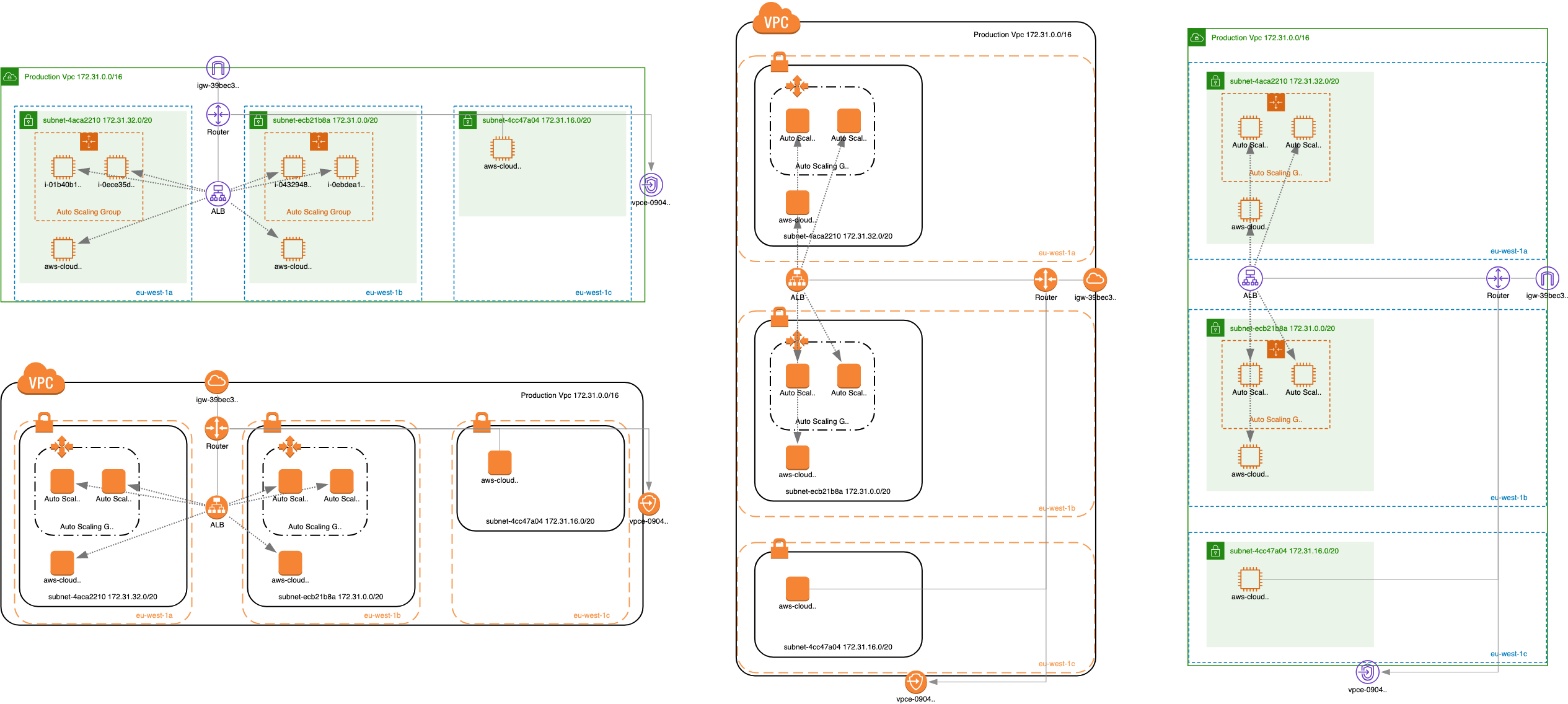
Simple VPC with Private/Public Subnets

Leverage this diagram to jumpstart the creation of your inaugural AWS architecture. Availability zones are horizontally aligned, and related subnets are vertically organized, offering a solid foundation for your design.
Serverless Web Application Architecture

This diagram presents a high-level example of an AWS serverless web application architecture, showcasing the main steps involved in utilizing various AWS serverless services:
- Request is sent from browser for domain name example.com
- DNS Resolver retrieves IP address from Route 53 (keep in mind that there are other DNS related queries before this) based on DNS record for example.com domain
- Route 53 has A alias record pointing to CloudFront distribution
- Browser sends request towards CloudFront distribution to retrieve static content files. In order to serve content over HTTPS there is generated TLS certificate for example.com in Certificate Manager and specified in CloudFront distribution configuration
- CloudFront requests static content files from S3 bucket and static content files are sent back to browser and processed there
- Browser sends new requests towards API Gateway to request necessary data (of course all the 1. and 2. steps are executed before in order to get IP address of API Gateway REST API)
- API Gateway sends request to Lambda for processing
- Lambda processes request and requests data from DynamoDB and then response is sent back all the way to browser
VPC Peering

Illustration showcasing a VPC peering architecture involving two requester and accepter VPCs. Demonstrates the inclusion of targeted routes within route tables to establish a secure and private connection between the VPCs.
AWS Organizations Setup

This diagram presents a high-level illustration of an AWS Organizations setup utilizing organizational units (OUs) and three AWS accounts. The diagram showcases the implementation of user access management through the utilization of cross-account roles, ensuring secure and controlled access across the organization.
Three Tier Web Architecture

In this example of a 3-tier architecture, the architecture diagram showcases the three essential layers: Presentation, Business Logic, and Data. The Presentation layer is represented by a CloudFront distribution, serving as the front-end, with two origins. One origin points to static S3 assets, while the other connects to a public Application Load Balancer (ALB) responsible for routing requests to EC2 instances, serving as web servers. The Business Logic layer is supported by an internal ALB, which routes requests to private EC2 instances functioning as application servers. Finally, in the Data layer, private RDS instances are depicted, including a master and replica instances, serving as the database backend for the application. Overall, this architecture diagram provides a clear visualization of the different layers and their corresponding components within the 3-tier architecture.
Two Tier Web Architecture

In this example of a 2-tier web architecture, the architecture diagram illustrates the two main layers: Presentation/Business Logic and Data. The Presentation/Business tier is represented by an Application Load Balancer (ALB) that efficiently routes incoming requests to EC2 instances, serving as both web and application servers. In the data layer, private RDS instances are depicted, including a master and replica instances, which handle the storage and management of the application's data. By visually representing this architecture, the diagram provides an overview of the components involved in the Presentation/Business Logic layer and the Data layer, offering insights into how the different layers interact and support the overall functionality of the web application.
Site-to-Site VPN Connection

This diagram demonstrates a site-to-site VPN connection between an Amazon VPC and a corporate data center. It showcases the secure channel established between the two, enabling the seamless exchange of data. The diagram provides a visual representation of the VPC, corporate data center, and the VPN tunnel connecting them, emphasizing the secure and direct communication between the two environments.
Amazon EKS and Worker Nodes

This diagram illustrates a straightforward setup of an Amazon Elastic Kubernetes Service (EKS) environment with worker nodes represented by EC2 instances. The worker nodes are deployed in private subnets to enhance security. To enable Secure Shell (SSH) access to these nodes, a bastion host is deployed in a public subnet. The diagram provides a visual representation of the network architecture, showcasing the segregation of resources and the utilization of a bastion host for secure remote access to the worker nodes.
Linux Bastion Host

The diagram above presents a basic setup of a Linux bastion host environment. The bastion host serves as a secure gateway to allow Secure Shell (SSH) access to EC2 instances that are deployed in private subnets. By employing the bastion host, administrators can securely access and manage the private EC2 instances without exposing them directly to the public internet. This design enhances the overall security of the architecture while providing a convenient and controlled method for remote access to the private EC2 instances.
EFS File System and EFS Mount Targets

The diagram illustrates an example of a VPC (Virtual Private Cloud) setup with an EFS (Elastic File System) file system. The EFS file system is connected to specific subnets through EFS mount targets, allowing EC2 instances in those subnets to access the shared file storage. Additionally, a bastion host is included in the architecture to enable Secure Shell (SSH) access to the EC2 instances located in the private subnets. The bastion host acts as a secure entry point for administrators to securely connect to and manage the private EC2 instances. This configuration ensures secure access to resources within the VPC while facilitating efficient file storage and management using the EFS file system.
VPC Endpoint Gateway

The diagram provides an example of a VPC (Virtual Private Cloud) configuration with an VPC endpoint gateway. When an VPC endpoint gateway is created, it is associated with a specific route table within the VPC. In the diagram, the instance located in the public subnet 10.0.2.0/24 can access Amazon S3 directly through the endpoint gateway. On the other hand, the instances in the second public subnet also have access to S3, but their requests will be routed through the internet gateway.
Looking for a tool to automatically generate AWS architecture diagram?
Try out Cloudviz.io and visualize your AWS cloud environment in seconds

As experienced AWS architects and developers, our mission is to provide users an easy way to generate stunning AWS architecture diagrams and detailed technical documentation. Join us to simplify your diagramming process and unleash the beauty of your cloud infrastructure
Support
Contact
Copyright © 2019 - 2026 Cloudviz Solutions SIA